PowerHub Settings
Users with PowerHub Admin access have full access to the available settings. Admins can add, edit and delete records in most of the areas except Grid Lines.
The settings determine the allowable values for certain dropdowns throughout the application.
Admin Menu
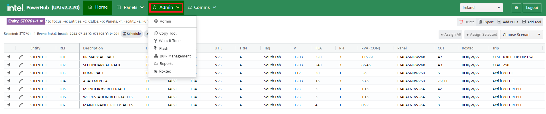
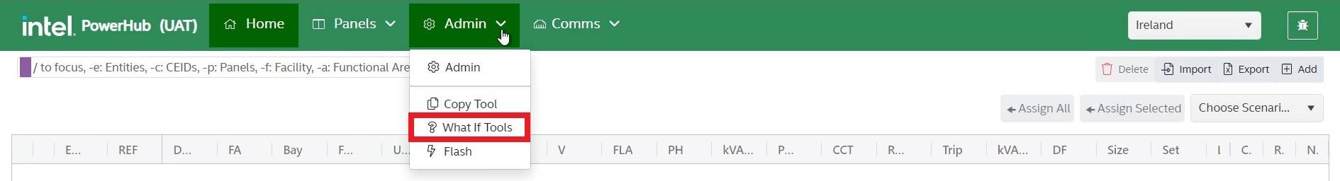
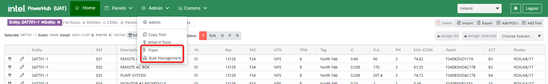
The Admin menu in PowerHub has 6 menu items:
-
Admin: used to configure the system for sites and facilities, described in detail below
-
Copy Tool: Used to copy or move power POCs from one tool to another, described below after the admin section
-
What If Tools: Used to add tool that can be assigned to panels without having an effect on the panel load calculations
-
Flash: The automated optimisation tool used for power pre-assignments. See Flash User Guide
-
Bulk management: Allows bulk upload/delete/export of data. See Data preparation for Flash page
-
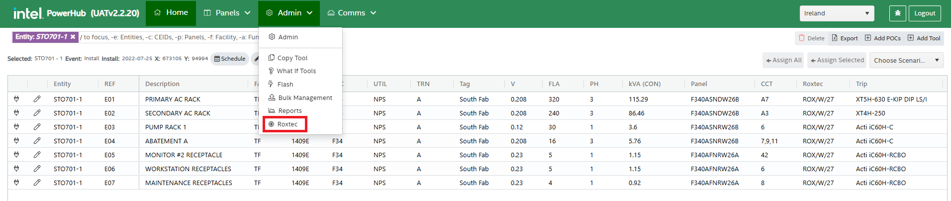
Roxtec: Used to view, add, edit, delete Roxtecs under a selected facility and site.
Admin Settings
Navigate to the Admin menu and select the Admin menu item.
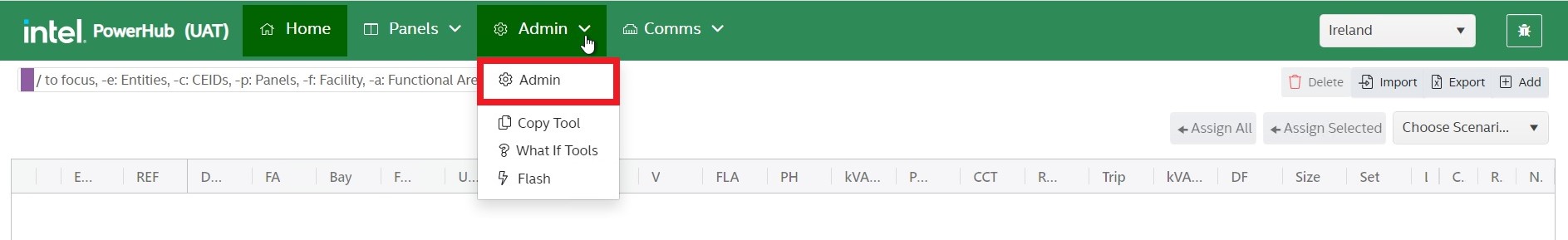
The configurable settings are listed down the left hand pane. Clicking on a setting title will load the settings page for that section.
A. Panel Config
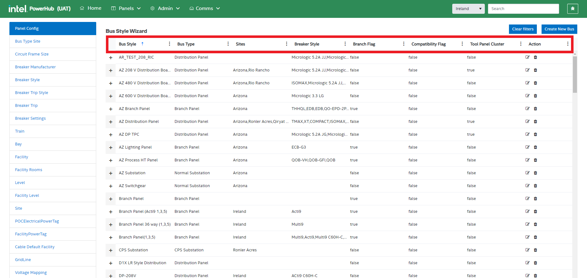
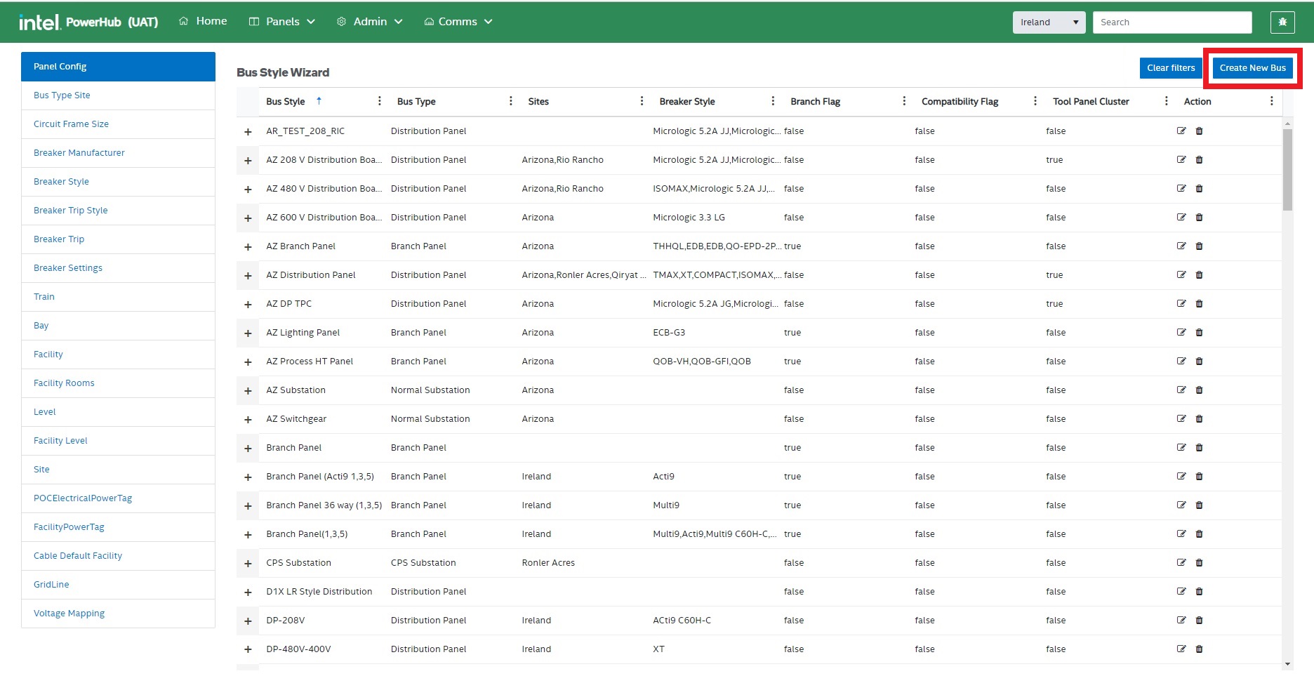
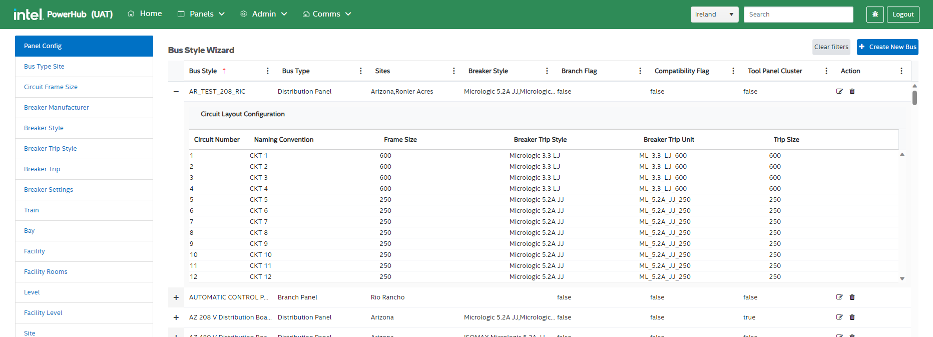
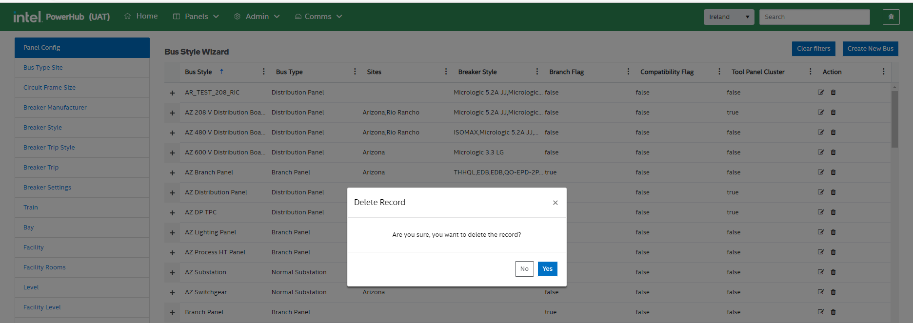
This is where power panel templates are configured. Each bus/panel in the system has a bus style, also known as a template. The grid lists all of the templates with some of their properties as shown in the table and image below.
| Attributes in Grid | Description |
| Bus Style | The template name |
| Bus Type | The types of bus are: Branch Panel, Distribution Panel, NPS/CPS/EPS Substations and Transformer. Transformer are onllt used so as they can be displayed in the panel tree hierarchy. |
| Sites | The Intel Sites where the panel templates are used. |
| Breaker Style | The breaker styles that are used in panels using of this bus style |
| Tool Panel Cluster | If distribution or branch panels are physically beside the substation, they are considered to be in a cluster. This means that the allowable voltage drop to those panels could be increased from 3% and 2% to 5%. Setting this value to true will enable the higher voltage drop. |
| Actions | The plus icon on the left expands the template to show how the circuits on the panel are configured. The icons on the right in the action column allow users to edit or delete Bus Style templates. |
Create New Bus
when you click the Create New Bus button on the top-right, the Create Bus Wizard is displayed with 3 steps: Panel Details, Breaker Style Compatibility, and Circuit Configuration.
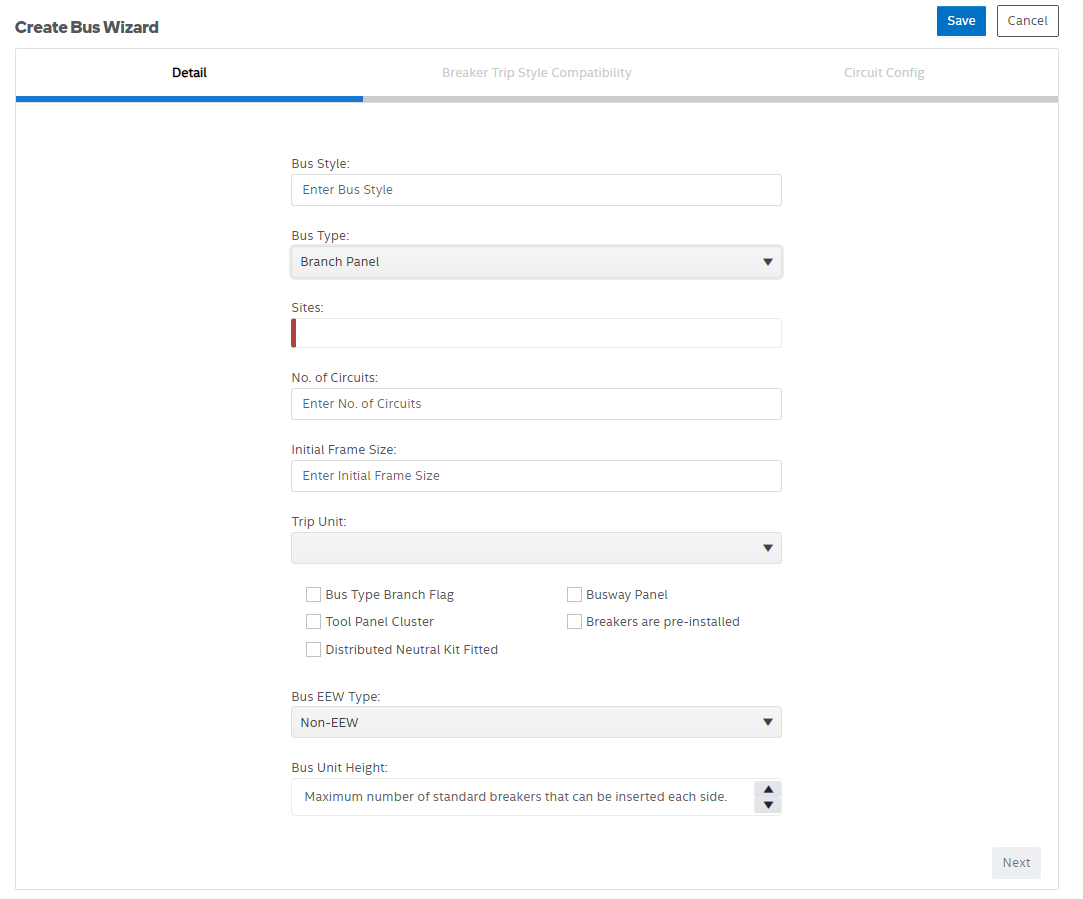
Panel Details
On the details page, you enter values for:
-
Bus Style (template name)
-
Bus Type (Branch Panel, Distribution Panel, NPS/CPS/EPS Substations and Transformer)
-
The site(s) the template will be used on
-
The number of circuits on the panels
-
The most common frame size on the panels
-
The most common trip unit used on these panels
-
Whether the panels using this style are Branch Panels
-
Whether the panels using this style form part of a tool panel cluster (this will affect allowable voltage drop on the panels)
-
Whether the panels using this style have a Distributed Neutral Kit Fitted (used in Penang)
-
Whether the panels using this style are busways that run the length of the facility (used in Penang)
-
Whether the panels using this style have breakers preinstalled when purchased
-
The EEW Type
-
Bus unit height
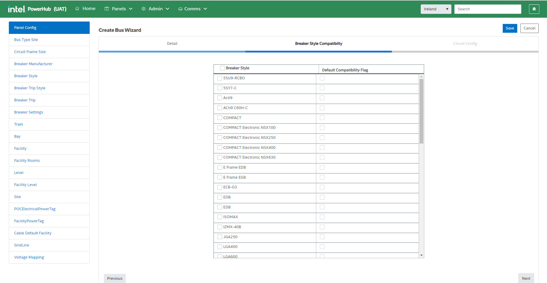
Breaker Style Compatibility
On the next step of the wizard, the user selects all of the breaker styles that can be used in the panels as well as the default one.
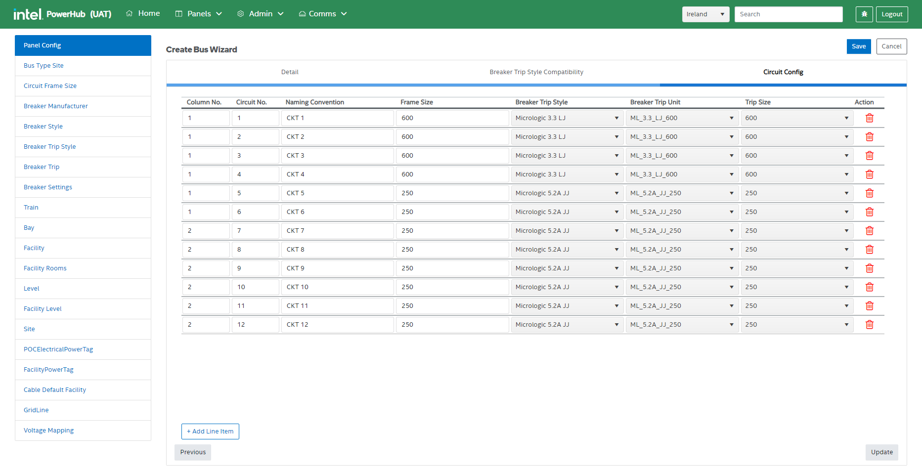
Circuit Configuration
On the circuit configuration step, the number of rows will be the number of circuits you entered and the frame size and trip unit will use the default values you selected on the details page. Enter the naming convention for each circuit (e.g. L1, L2, L3 etc.) and click create to save the new template.
You can also enter the Breaker Trip Style, Breaker Trip Unit and Trip Size for each circuit. These can then be used to set the breakers on individual panels where breakers come preinstalled.
Panel template circuits
Clicking the plus icon before a templates name expands the template to show the circuit details on the template.
This will display a grid showing the panel template’s circuit configuration including the circuit numbers, naming convention, frame size, breaker trip style, breaker trip unit and trip size.
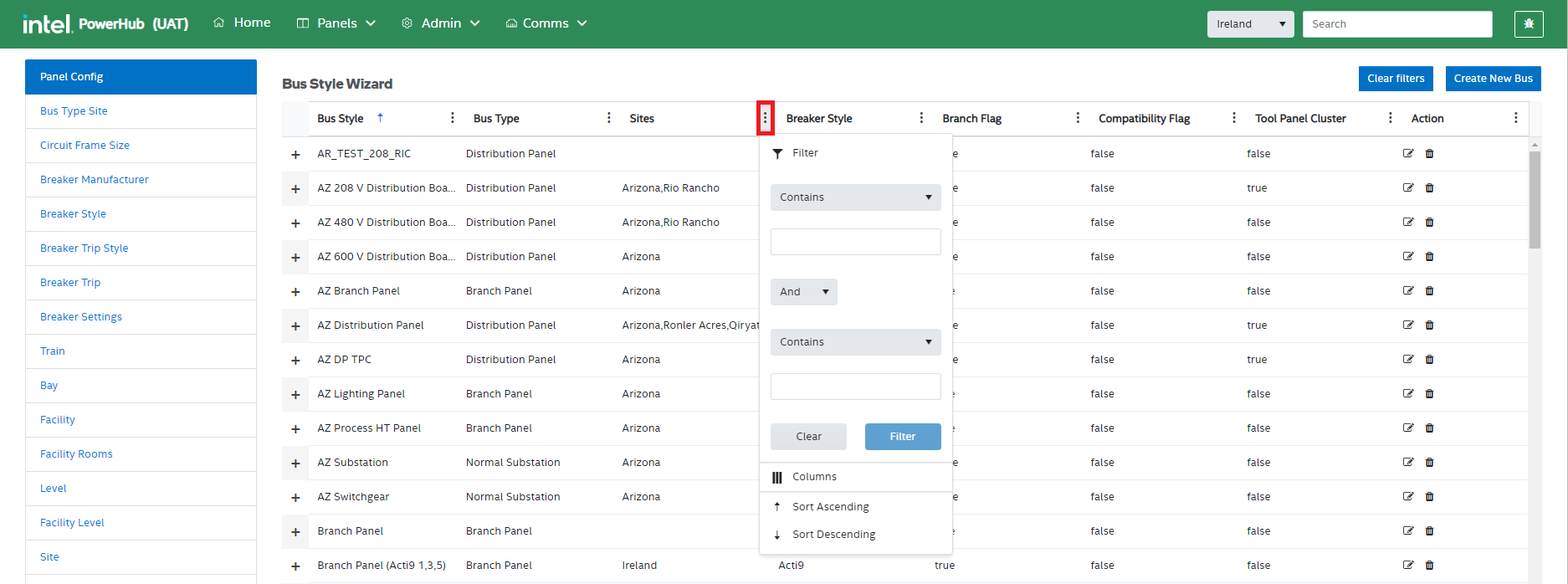
Filters
You can filter the values in the grid for any of the attributes.
For example, you can filter the values for “Sites” in the grid by clicking on the vertical ellipsis button and specifying the filter condition such as “Contains”, “Starts with”, and so on.
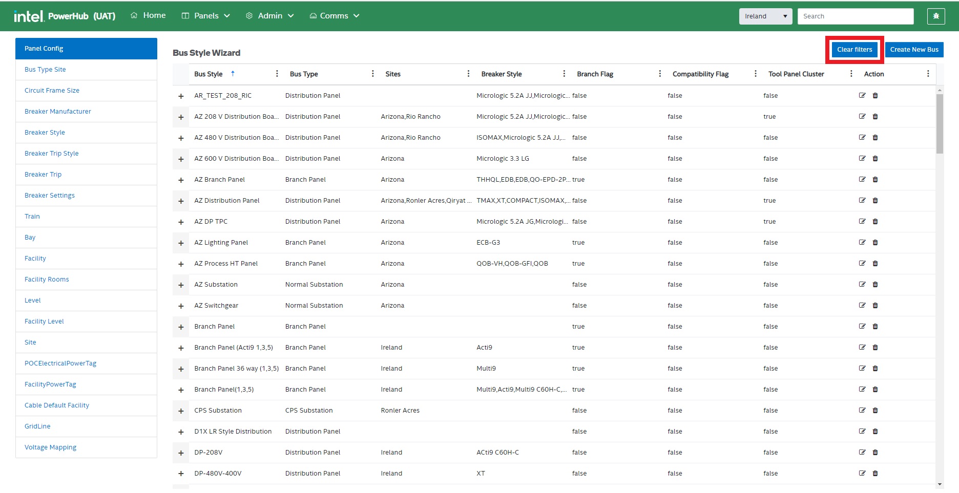
Clear Filters
Remove all the filters applied to any of the attributes in the grid.
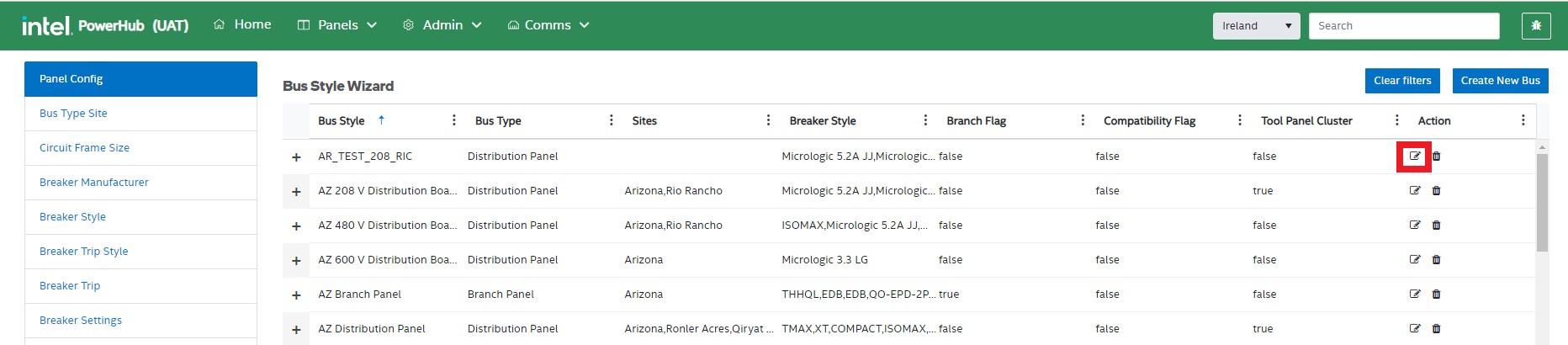
Edit
Click on the edit icon to update the information for an existing panel.
Delete
Click on the trash icon for any of the listed records in the grid to remove it. A confirmation modal window will appear. Click on Yes to confirm the delete operation.
If there are any panels that are using a template then you will not be able to delete it. To delete a template you need to delete all the panels of the same bus type first and then delete the template.
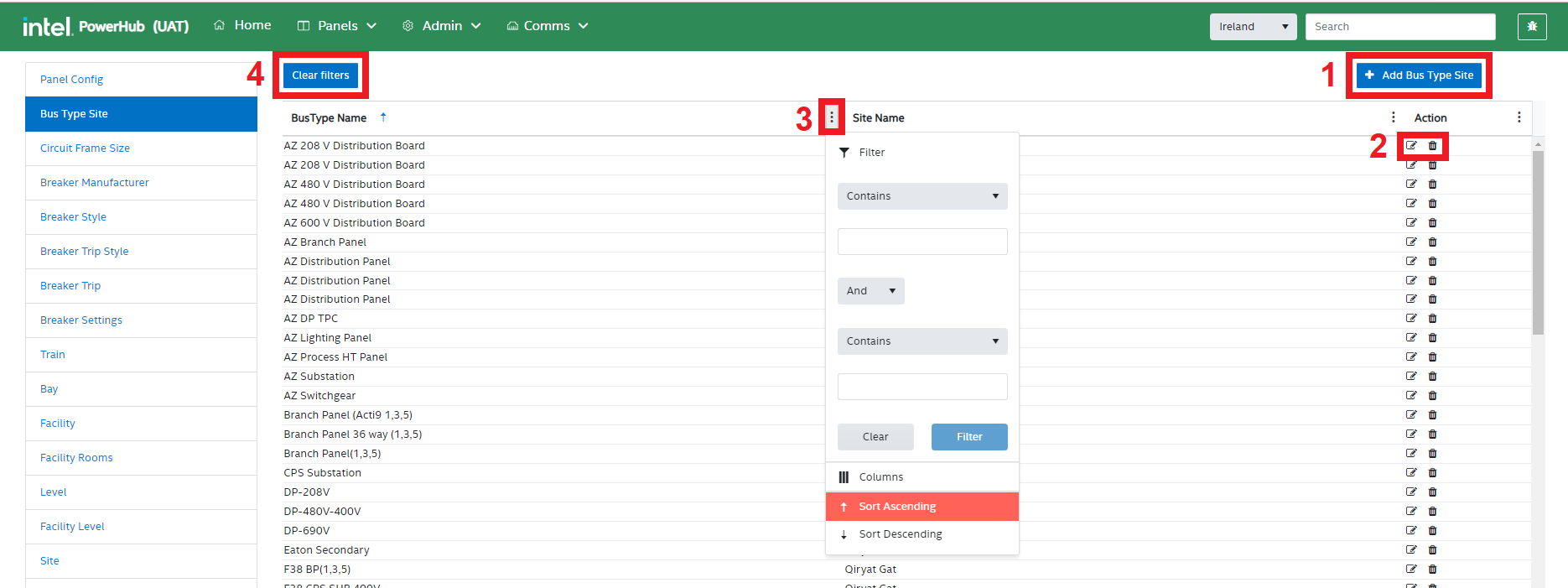
B. Bus Type Site
This setting give easy access to the sites that each bus style is used on. This is the same information as in the bus styles “Site” column, however, it displays a record for each template/site combination.
Bus Type Site functions
Users can perform the following operations in the Bus Type Site module:
-
Add Bus Type Site
-
Edit & Delete Bus Type Site
-
Filter a Bus Type Site Attribute
-
Clear Filters
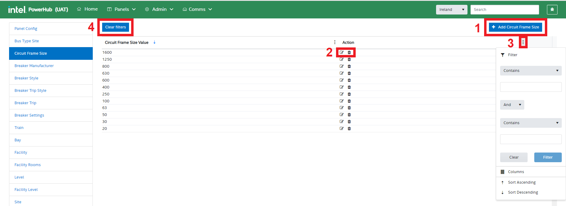
C. Circuit Frame Size
This setting allows users to view and configure all of the possible frame sizes used across all panels,
Circuit Frame Size functions
Users can perform the following operations in the Circuit Frame Size module:
-
Add Circuit Frame Size
-
Edit & Delete Circuit Frame Size
-
Filter a Circuit Frame Size Attribute
-
Clear Filters
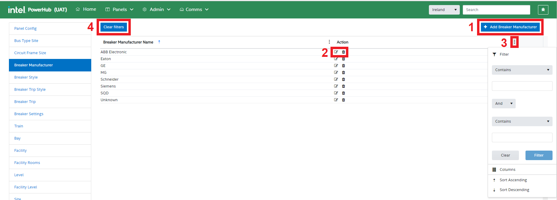
D. Breaker Manufacturer
This setting allows users to view and configure Breaker Manufacturers
Breaker Manufacturer functions
Users can perform the following operations in the Breaker Manufacturer module:
-
Add Breaker Manufacturer
-
Edit & Delete Breaker Manufacturer
-
Filter a Breaker Manufacturer Attribute
-
Clear Filters
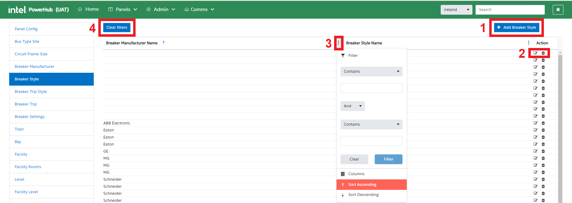
E. Breaker Style
This setting allows users to view and configure Breaker Styles per manufacturer
Breaker Style functions
Users can perform the following operations in the Breaker Style module:
-
Add Breaker Style
-
Edit & Delete Breaker Style
-
Filter a Breaker Style Attribute
-
Clear Filters
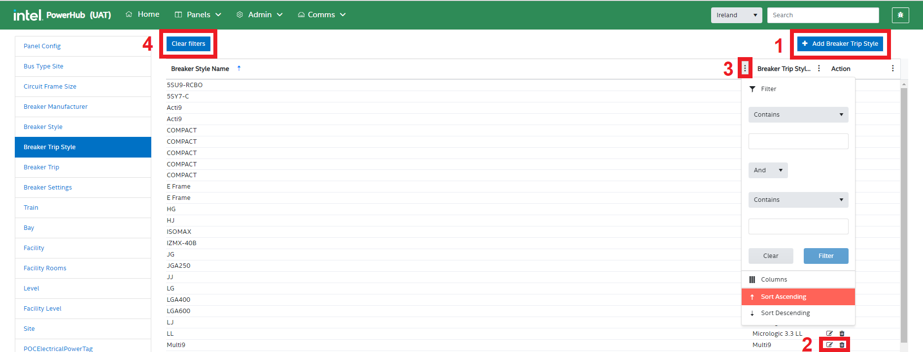
F. Breaker Trip Style
This setting allows users to view and configure multiple Breaker Trip Styles for each Breaker Styles
Breaker Trip Style functions
Users can perform the following operations in the Breaker Trip Style module:
-
Add Breaker Trip Style
-
Edit & Delete Breaker Trip Style
-
Filter a Breaker Trip Style Attribute
-
Clear Filters
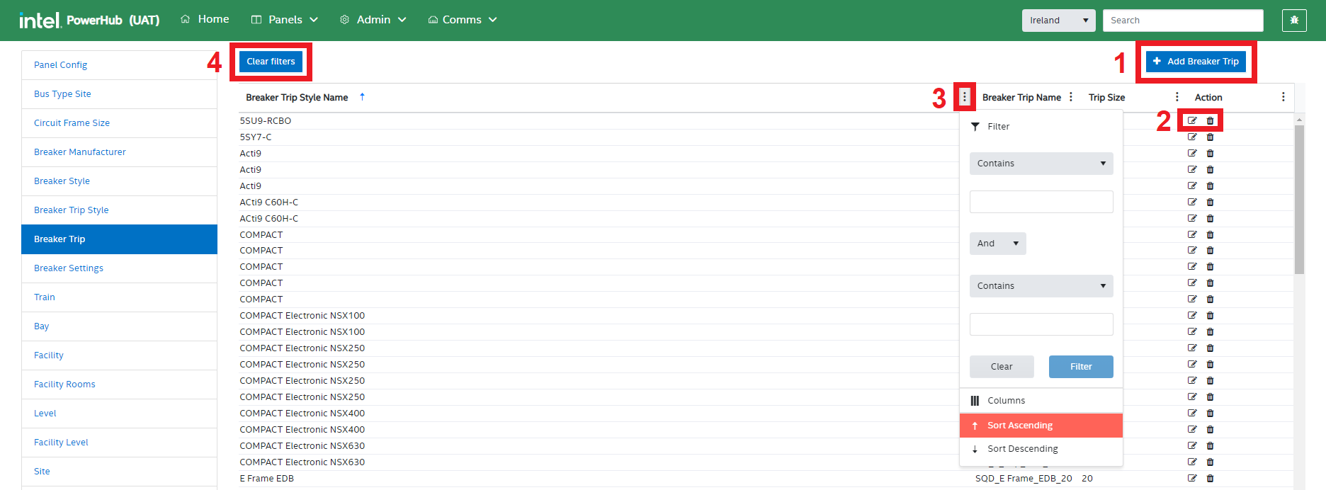
G. Breaker Trip
This setting allows users to view and configure multiple Breaker Trips for each Breaker Trip Style
Breaker Trip functions
Users can perform the following operations in the Breaker Trip module:
-
Add Breaker Trip
-
Edit & Delete Breaker Trip
-
Filter a Breaker Trip Attribute
-
Clear Filters
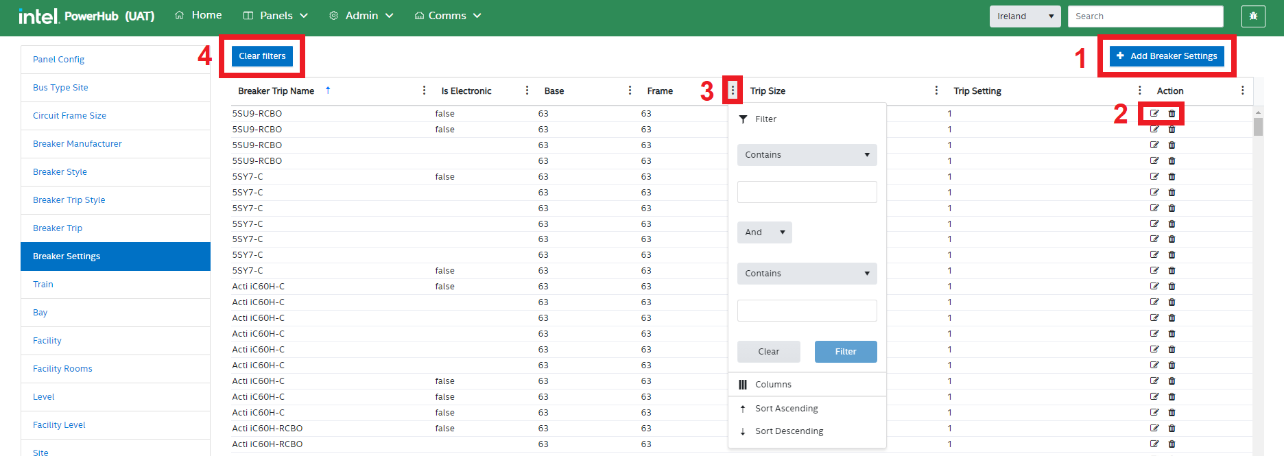
H. Breaker Settings
This setting allows users to view and configure multiple Breaker Settings for each Breaker Trip. Non adjustable breakers will have only one setting equal to the trip value. Adjustable breakers will have multiple settings as a percentage of the max trip.
Breaker Settings functions
PowerHub admin users can perform the following operations in the Breaker Settings module:
-
Add Breaker Setting
-
Edit & Delete Breaker Setting
-
Filter a Breaker Setting Attribute
-
Clear Filters
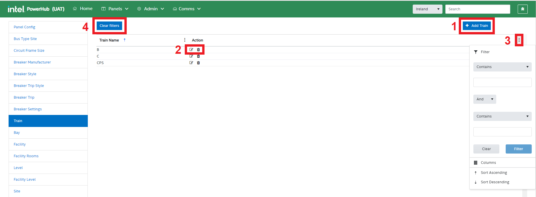
I. Train
This setting allows admin users to view and configure power supply trains available in the system. Each panel and each POC has a train and POCs can only be assigned to panels with the same train. Most Panels are on one of 3 power trains: “A”, “B”, or “C”. Other power trains are used for specific purposes in selected sites. Generally when preassigning POCs user attempt to ensure that tools of the same CEID are spread evenly across trains “A”, “B”, and “C”.
Train settings functions
PowerHub admin users can perform the following operations in the train settings module:
-
Add a train
-
Edit & Delete trains
-
Filter the grid
-
Clear Filters
J. Bay
This setting allows admin users to view and configure the Bays within each facility. Power panels are assigned to specific Bays. Generally Bays will appear automatically in PowerHub as they appear in the P3 schedule. Bays would usually only be added by perrons doing what if analysis on future tools.
Bay settings functions
PowerHub admin users can perform the following operations in the Bay module:
-
Add Bay
-
Edit & Delete Bay
-
Filter the grid of Bays
-
Clear Filters
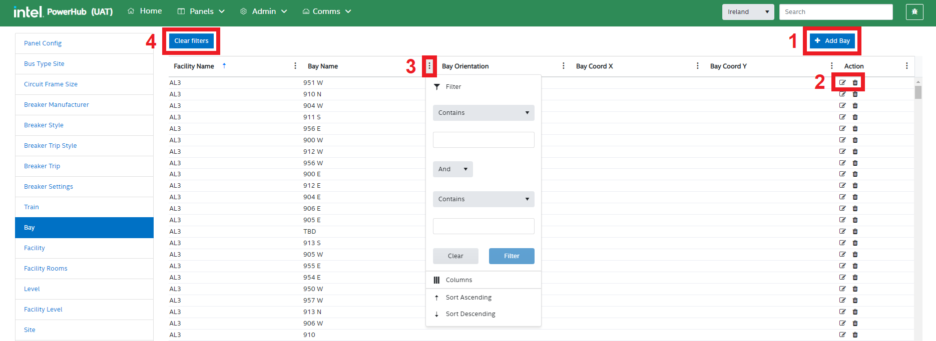
A bay cannot be deleted if there are panels associated with that bay.
K. Facility
This setting allows admin users to view and configure the different facilities in each site. The facilities users see in PowerHub are those from the P3 schedule. In other systems (such as FaSTr) you may see different names on facilities but it is the P3 schedule facility that takes precedence. Multiple facilities in FaSTr may be referenced as a single facility in PowerHub and multiple facilities in PowerHub may be referenced as a single facility in FaSTr. Generally facilities will appear automatically in PowerHub as they appear in the P3 schedule.
Facility settings functions
PowerHub admin can perform the following operations in the Facility module:
-
Add a Facility
-
Edit & Delete Facility
-
Filter the grid
-
Clear the Filters
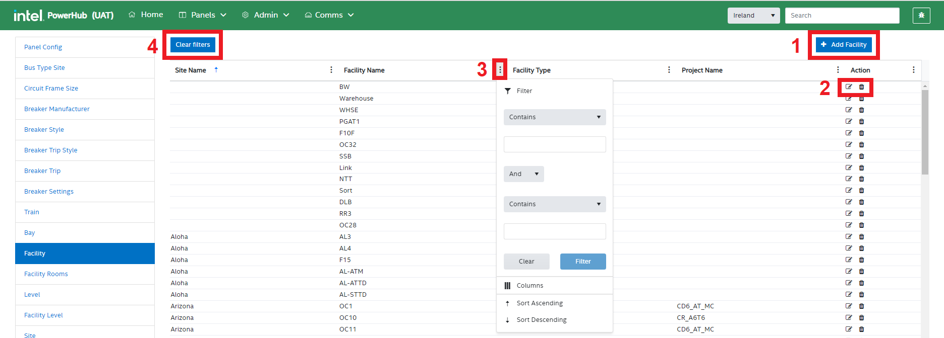
A facility cannot be deleted if there are panels or tools associated with that facility.
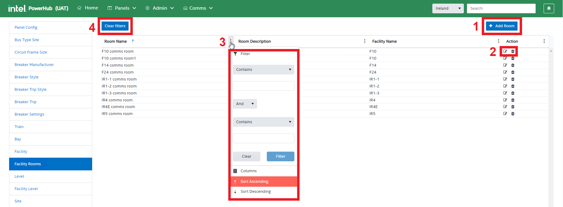
L. Facility Rooms
This setting allows admin users to view and configure the different rooms in each facility. Usually rooms are only used for CommsHub to specify the location of comms server panels.
Facility Rooms settings functions
PowerHub admin users can perform the following operations in the Facility Rooms module:
-
Add a Room
-
Edit & Delete Rooms
-
Filter the grid
-
Clear Filters
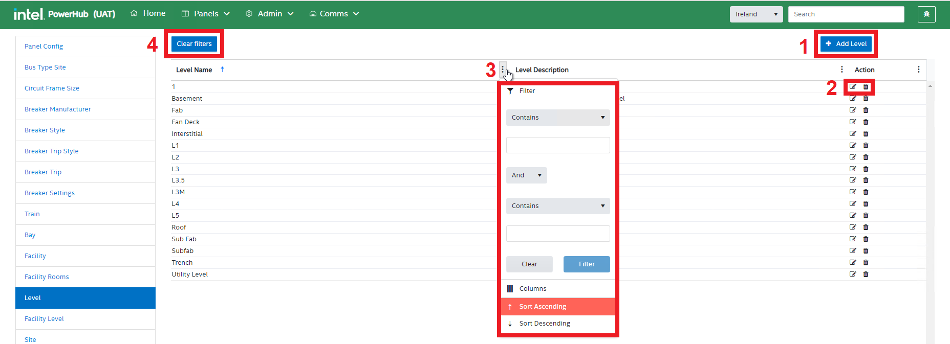
M. Level
This setting allows admin users to view and configure the different levels that may be in facilities. It is a list of possible levels, the individual levels in each facility are configured in the next section.
Level settings functions
PowerHub admin can perform the following operations in the Level module:
-
Add a Level
-
Edit & Delete Levels
-
Filter the grid
-
Clear Filters
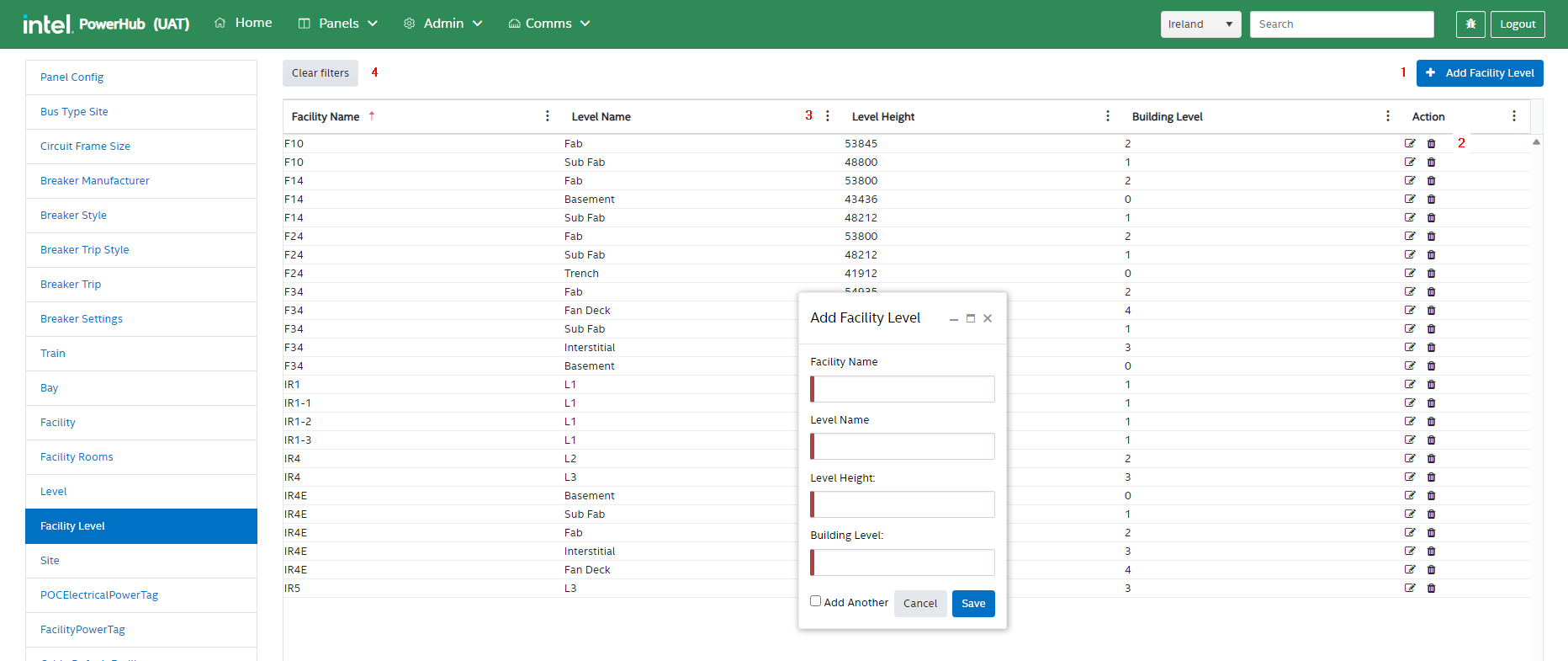
N. Facility Level
This setting allows admin users to view and configure the levels that exist in each specific facility. Generally a standard Fab will have the following Levels:
-
Utility/Basement/Trench
-
Sub Fab
-
Fab
-
Interstitial
-
Fan Deck
The floor/level that a Power panel or a POC is on can be set to one of the levels available in the POC’s or panel’s facility. Each level in each facility can have a height in inches (USA) or millimetres (outside US). These values are inches or millimetres above sea level as provided by layout drawings. The difference in the height value of two levels give you the vertical distance between the floor of those two levels.
Facility Level settings functions
PowerHub admin users can perform the following operations in the Facility Level module:
-
Add a Facility Level
-
Edit & remove a level from a facility
-
Filter the grid
-
Clear Filters
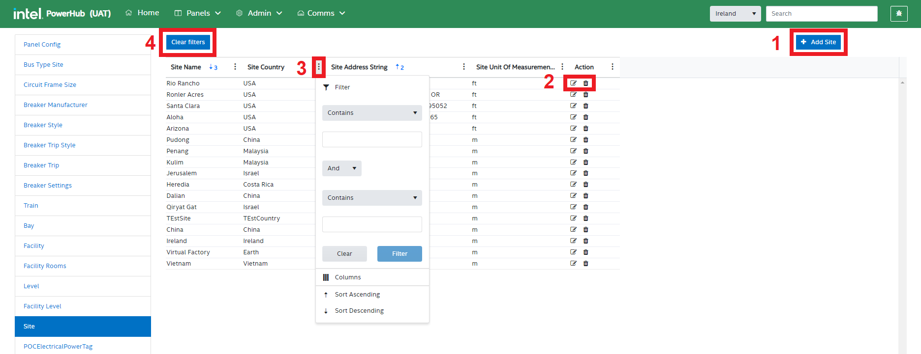
O. Site
This setting allows admin users to view and configure the sites that exist in the PowerHub system. Sites in the USA will have an electrical frequency of 60 Hz and and will use imperial (feet/inches) measurements. Sites in the rest of the world will have an electrical frequency of 50 Hz and and will use metric (metres/millimetres) measurements.
Site settings functions
PowerHub admin can perform the following operations in the Site module:
-
Add a Site
-
Edit & Delete Sites
-
Filter the grid
-
Clear Filters
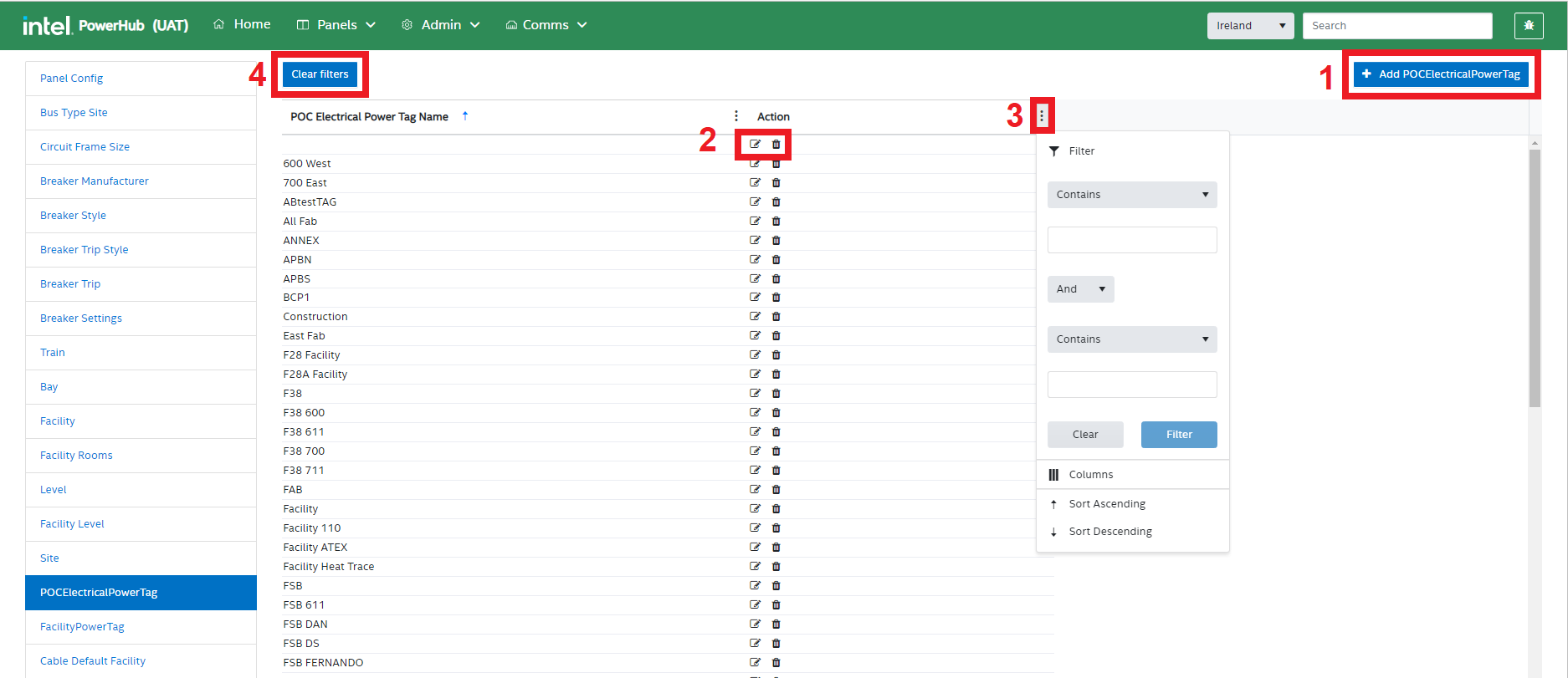
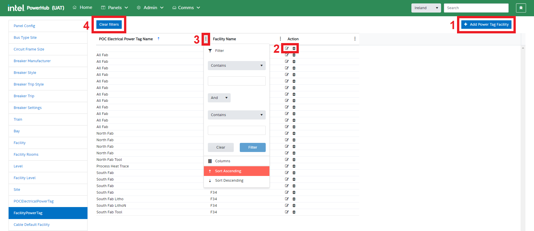
P. POC Electrical Power Tag
This setting allows admin users to view and configure Power Tags. It is a list of possible power tags across all sites, The individual tags used in each facility are configured in the next section. Power tags are used to group panels in areas within a fab to ensure that POCs are assigned to a local set of panels. The tags are set on the panels and on the POCs. A POC can only be assigned to panels that share the same tag as the POC. This helps prevent assigning a POC to a panel which may be physically close to the tool but which cannot be reached due to a physical obstruction such as a firewall.
POC Electrical Power Tag settings functions
PowerHub admin can perform the following operations in the POCElectricalPowerTag module:
-
Add Power Tag
-
Edit & Delete tags
-
Filter the gris
-
Clear Filters
Q. Facility Power Tag
This setting allows admin users to view and configure the power tags that exist in each specific facility. When editing a POC or a Panel, only the power tags that are set for that facility will be selectable in the panel and POC edit pages.
Facility PowerTag settings functions
PowerHub admin can perform the following operations in the FacilityPowerTag module:
-
Add a Facility Power Tag
-
Edit & remove tags from facilities
-
Filter the grid
-
Clear Filters
R. Cable Default Facility
This setting is not operational
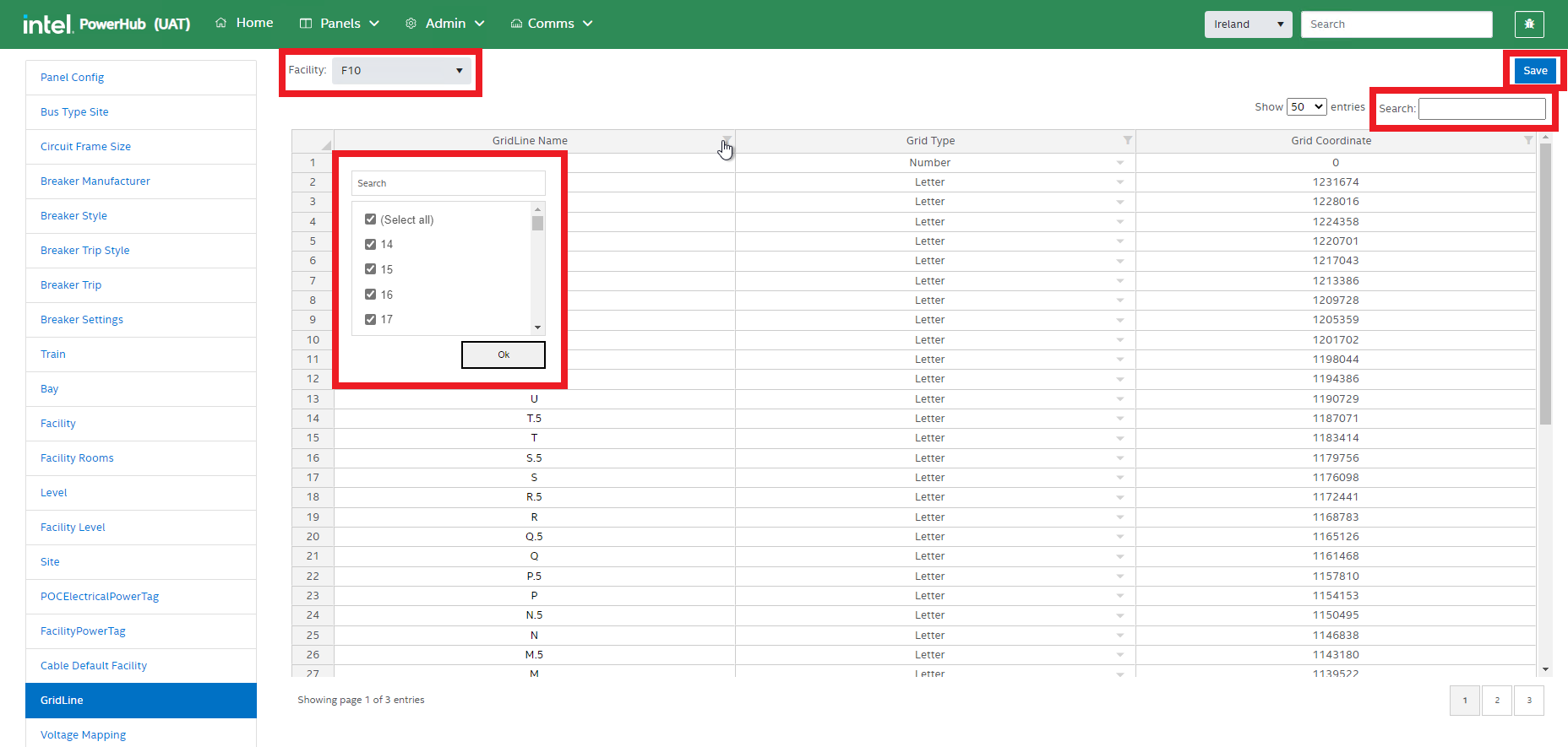
S. Grid Lines
This setting allows admin users to view and configure the power grid lines in a facility. Gridlines can be imported and updated on the Data preparation for Flash page
Grid Line operations
PowerHub admin can perform the following operations in the GridLine module:
-
Filter the data on the basis of Facility
-
Filter a the grid
-
Search any data in Grid
-
Insert a new gridline record by right clicking, populating the grid and clicking “Save”
T. Voltage Mapping
This setting allows admin users to view and configure voltage mappings for specific facilities. Some countries that use 50Hz power supplies do not use 230V (single phase) and 400V (three phase). They may use 220V/380V or 240V/415V. These settings are used to convert voltages in FaSTr as 230V/400V to the correct local voltage in PowerHub.
Voltage Mapping CRUD operations
PowerHub admin can perform the following operations in the Voltage Mapping module:
-
Add Voltage Mapping
-
Edit & Delete Voltage Mapping
-
Filter the grid
-
Clear Filters
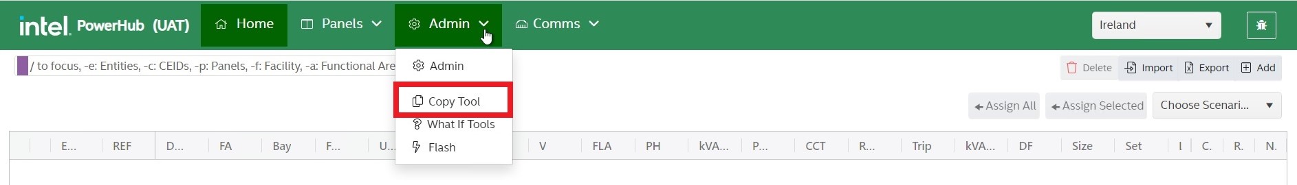
Copy Tool
This module allows admin users to copy or move power and telecom POCs from one tool to another tool. Copying assignments will also copy the Popout/Roxtec assignments as well as panel/CP assignments.
Select the Admin menu from the top and select the Copy Tool option from the drop-down list.
A pop-up window opens that gives the admin a choice to copy or transfer a tool. You can select either “Copy” or “Transfer”
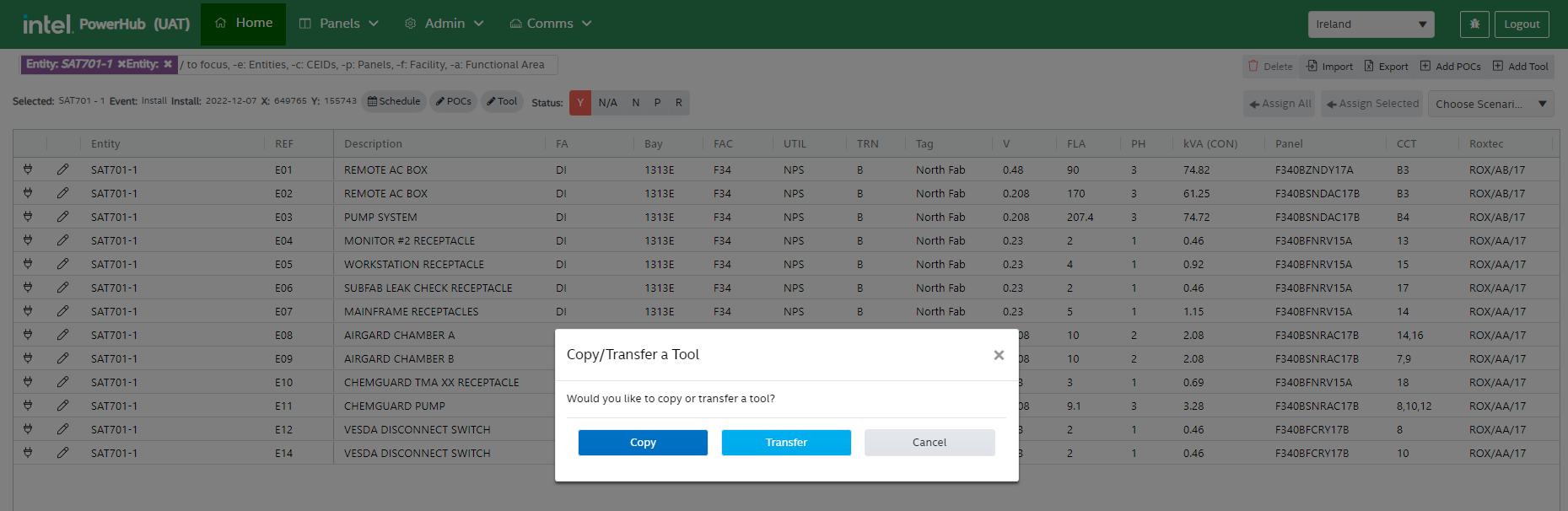
Copy
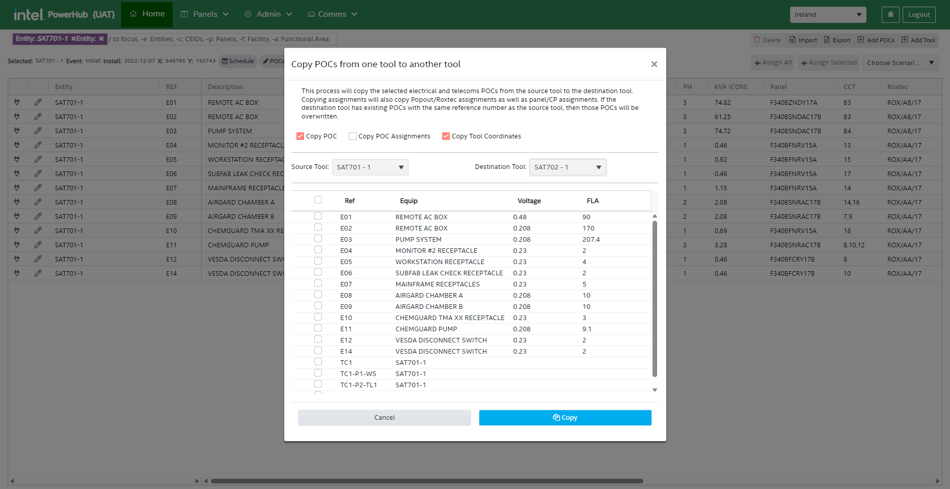
This process will copy the selected electrical and telecoms POCs from the source tool to the destination tool. Copying assignments will also copy Popout/Roxtec assignments as well as panel/CP assignments. If the destination tool has existing POCs with the same reference number as the source tool, then those POCs will be overwritten.
Clicking the “Copy” button displays the dialog below with the following features:
Copy POC - If selected, POCs are copied from the source tool to the destination tool.
Copy POC Assignments - If selected, POC assignments are copied from the source tool to the destination tool.
Copy Tool Coordinates - If selected, tool coordinates are copied from the source tool to the destination tool.
Source Tool - When the user selects a source tool the grid populates with bote power POCs and telecoms POCs. You can select the POCs you want to copy from the grid.
Destination Tool - Enter destination tool
If the source tool entity name doesn’t match the destination tool entity name, you will get a warning because, in the majority of the cases, POCs are transferred from one life to the next life on the same tool. You can ignore this warning or select the same tool with a different number of life for the source tool and destination tool.
Once source and destination tools are selected, clicking the Copy button makes a copy of the selected POCs from the source to the destination.
Copying assignments will mean that there are two sets of POCs connected to the same set of panels. This is okay if you are copying POCs from one life of a tool to another life of the same tool. It is important that the “Active From” date on the newer life is set to a date after the “Active To” date of the old life, otherwise it will appear as if panel circuits have duplicate assignments.
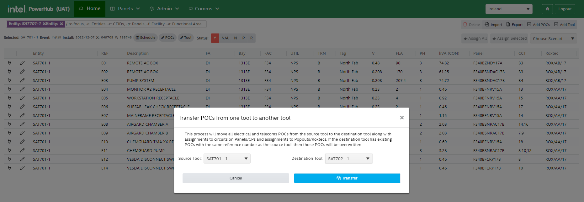
Transfer
If the admin clicks the Transfer button, a transfer POCs window will display. This process will move all electrical and telecoms POCs from the source tool to the destination tool along with assignments to circuits on Panels/CPs and assignments to Popouts/Roxtecs. If the destination tool has existing POCs with the same reference number as the source tool, then those POCs will be overwritten.
In most cases, the transfer function is used to move POCs from one life to the next life on the same tool, e.g., From ANT701-3 to ANT701-4. Physically it is the same tool in the same position.
What If Tools
This module allows the admin user to add, edit, delete tools that are not on the P3 schedule, and associate POCs with them. What if tools are used to simulate possible future scenarios to see what would happen if those tools were assigned to power panels.
Select the Admin menu from the top and select the What If Tools option from the drop-down list.
A grid listing all the what if tools on your site is displayed.
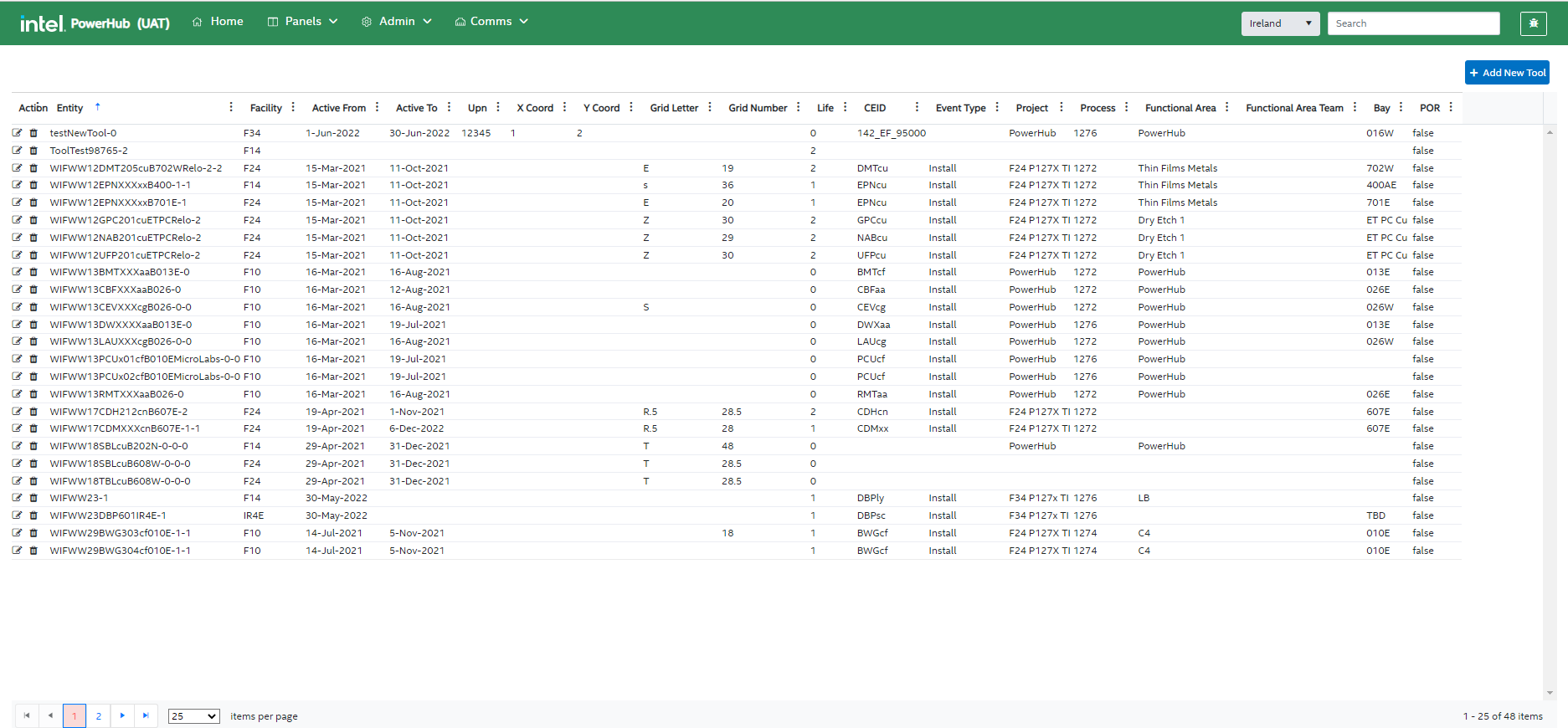
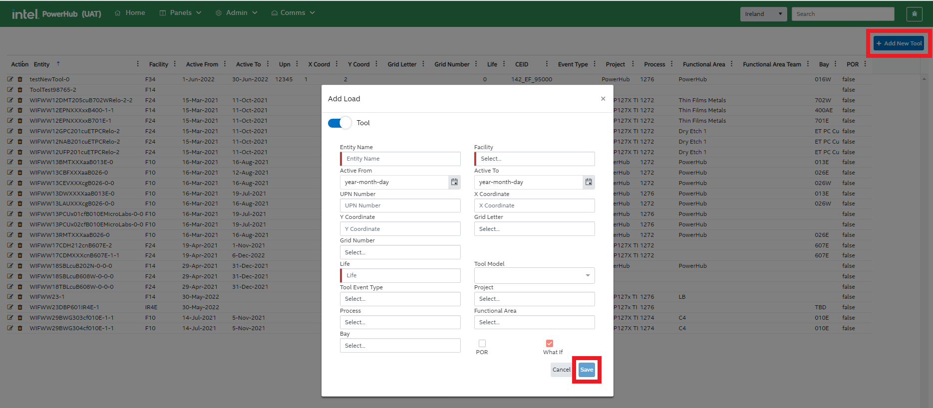
Add New Tool
Users can a new tool to PowerHub. When you click the “Add New Tool” button, a new modal window opens. Enter the tool entity name, facility, and life. The “What If” checkbox will be checked and the “POR” checkbox will be unchecked
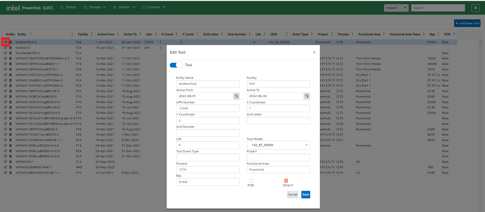
Edit Tool
You can click the pencil icon to the left of a tool in the grid to to update the tool details such as entity, facility, UPN, grid letter, grid number, active from, active to, etc.
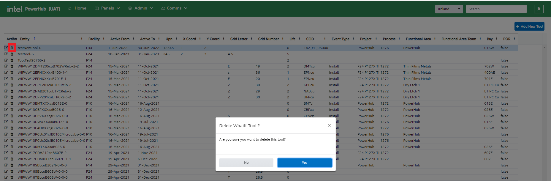
Delete Tool
Delete a What If tool by clicking on the delete icon on the left. A confirmation dialog pops up. Click Yes to remove the tool.
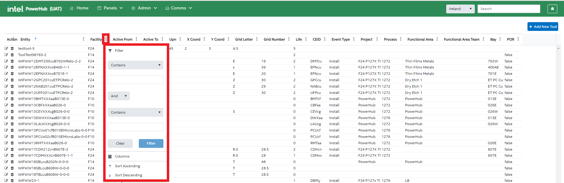
Filter Tools in the grid
Filter the values in the grid for any of the attributes by specifying the conditions of your choice.
For example, you can filter the values for “Facility” in the grid by clicking on the adjacent vertical ellipsis button and specifying the filter condition to filter the data.
Flash
Flash is used for automatic POC assignments to the panels. Please refer to the Flash User Guide for more information
Bulk data management
Allows bulk upload/delete/export of data. See Data preparation for Flash page
Roxtec management
This module allows the admin users to view, add, edit, delete Roxtecs under a selected facility and site.
Select the Admin menu from the top and select the Roxtec option from the drop-down list.
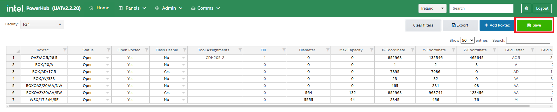
Roxtec page with a Facility dropdown and a grid that lists all Roxtecs for the selected facility and site are displayed.
The Facility dropdown displays only facilities that contain Roxtecs, listed in alphabetical order. By default, the first facility in alphabetical order is selected, and users can use this dropdown to choose a different facility if needed.
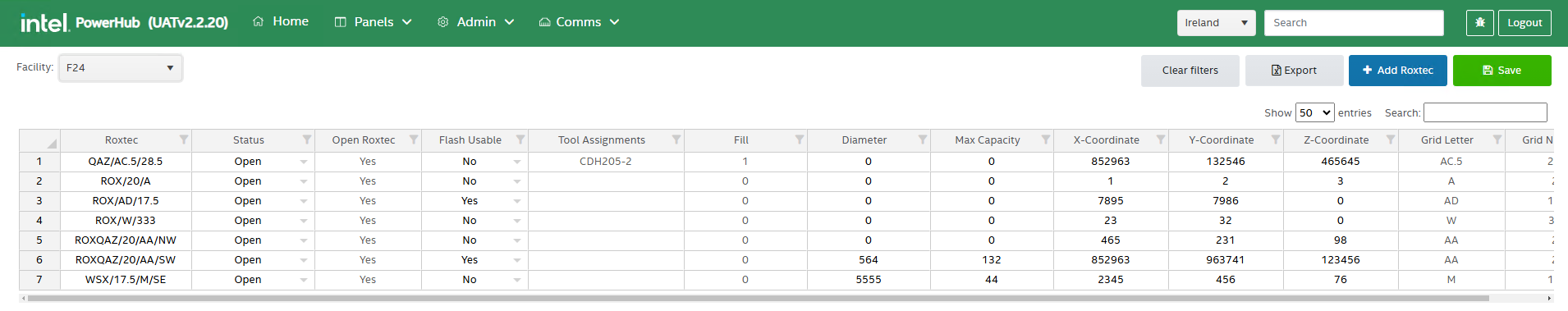
Flash Usable Field
The Flash Usable field in the grid indicates whether a Roxtec is available for flash or not, regardless of its current status. This is an editable field within the grid, allowing users to change its value from "No" to "Yes" to make a Roxtec available for flash.
- Users can set the Flash Usable field to "Yes" to mark a Roxtec as available for flash.
- Any updates to the Status field will automatically reset the Flash Usable field to align with the new status.
- If the user has previously modified the Flash Usable field, this custom setting will be cleared, and the field will revert based on the updated Status value.
- Users will need to manually update the Flash Usable field again if a specific value is required after a status change.
Updating a Roxtec
In the Roxtec grid, the first column ‘Roxtec’ displays the Roxtec Name. To update or rename a Roxtec, double-click on the Roxtec you wish to rename. The cell will switch to editable mode. Enter the new name as needed, then click the Save button to update the name in the grid.
The Roxtec name must satisfy below conditions:
- The Roxtec name must include at least two forward slashes (/) and
- The Roxtec name must contain a valid grid letter and grid number that correspond to the selected facility and site.
- If the Roxtec name has fewer than two forward slashes (/), an error message will be displayed as: “Roxtec name must contain at least two forward slashes (/) and include one valid grid letter and one valid grid number (e.g., ROX/AA/11 or ROX/11/AA).”
- If the Roxtec name includes a grid letter or number that doesn’t correspond to the selected facility and site, an error message will be displayed as: “Invalid grid letter or number. Please use a valid grid letter and number available under the selected facility.”
- If the entered Roxtec name already exists, an error message will be displayed as: “ROX/XX/XX already exists. Please enter a unique Roxtec name with a different grid letter and number.”
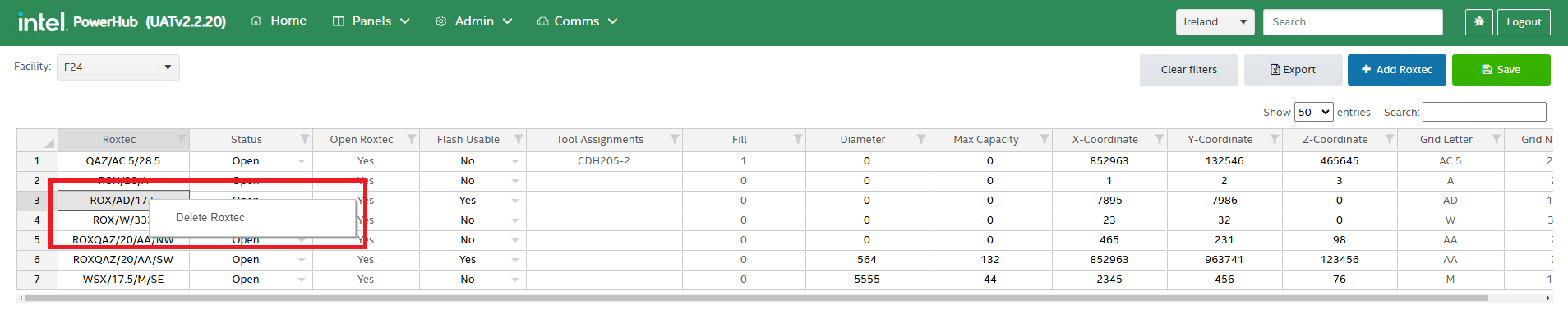
Deleting a Roxtec
Right click on the roxtec to see ‘Delete Roxtec’ option on the right clcik contex menu. Select this option to delete the roxtec.
The system will validate if there are any tool assignments on the roxtec before deleting the Roxtec.
- If there are assignments, user will get a message as “Roxtecs with assignments cannot be deleted” and the roxtec will not get deleted from the grid.
- If there are no assignments, user will get a popup window with 'YES' or 'NO' options. Clicking 'YES' will remove the roxtec from the grid. Clicking 'NO' will not remove the roxtec from the grid.
Other Options on the Roxtecs Page
The roxtecs page has below options:
- Grid filters
- Search box
- Clear Filters button
- Export button
- +Add Roxtec button
- Save button
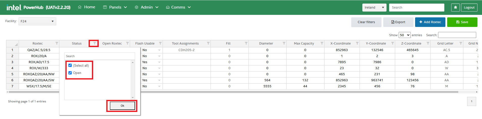
1. Grid filters
Grid filters allow users to filter data within each column of the grid. Here is how to use them:
- Access Grid Filters: Each column in the grid has filter icon next to the column. Click on the filter icon next to the column you want to filter to see a list of all values in that column.
- Select/Unselect Values: By default, all values are selected. Use the checkboxes to select or unselect specific values you want to display in the grid.
- Apply Filter: After making your selections, click OK to apply the filter and view the filtered results in the grid.
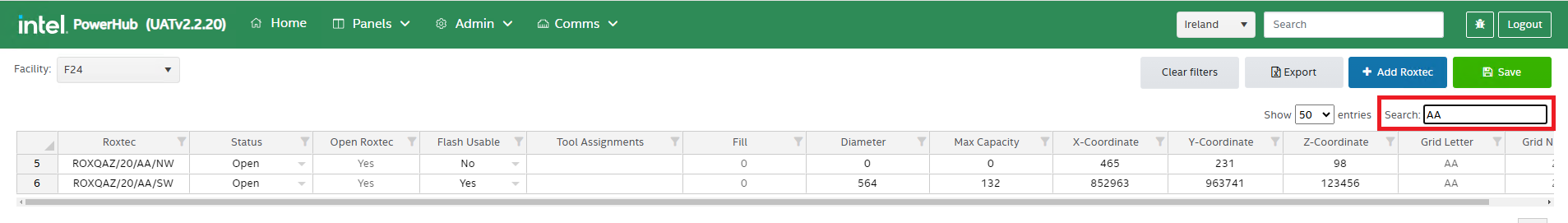
2. Search Box
The Search Box filters the entire grid based on a specific value across all columns. To Search, type a value into the search box, the grid will then automatically display rows where the search term appears in any column. This feature makes it easy to locate entries containing specific values across the grid.
3. Clear Filters Button
The Clear Filters button removes all active filters on the grid, including both column filters and any search box filters. Click the Clear Filters button to remove all applied filters and display the full, unfiltered grid. This option is helpful for quickly resetting the grid to its original view.
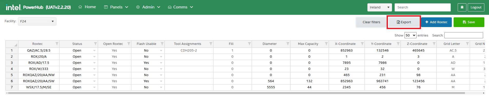
4. Export Button
The Export button allows users to download the grid data as an Excel file. Click the Export button to download the data as an Excel file with name Roxtec.xlsx. This feature provides an easy way to save and share the grid data.
- If no filters are applied, the entire grid data will be exported.
- If filters are applied, only the filtered data will be included in the export.
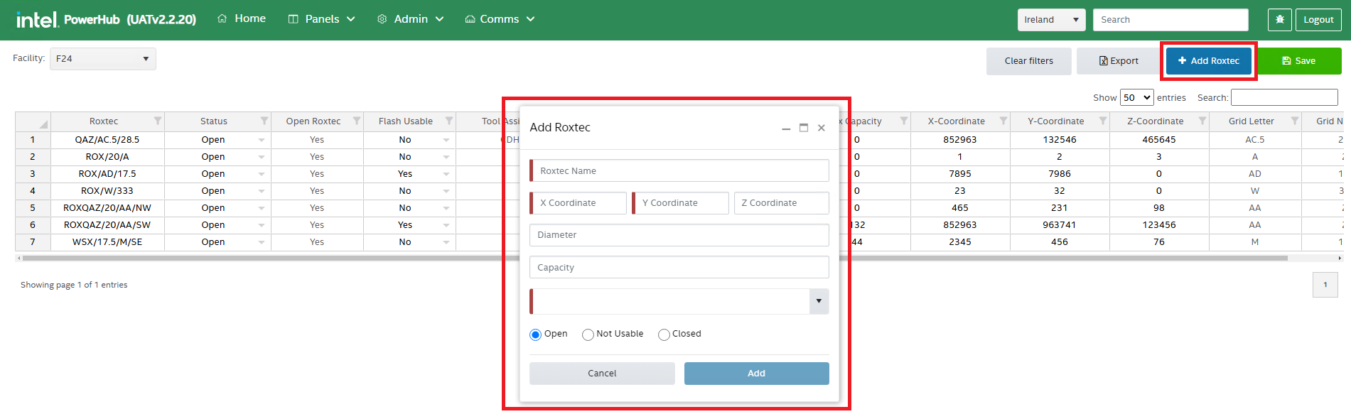
5. '+Add Roxtec' Button
The +Add Roxtec button allows users to add a new Roxtec entry to the grid under the selected facility and site. Click the +Add Roxtec button, an Add Roxtec popup window will appear. Fill in the required details as described below, then click Add button on the popup window to save the new Roxtec to the grid.
Fields in Add Roxtec Popup:
- Roxtec Name: It's a mandatory field. Refer to the "Updating a Roxtec" section in this guide for roxtec naming conditions.
- X Coordinate It's a mandatory field. Only numerical values are accepted, including negative numbers.
- Y Coordinate It's a mandatory field. Only numerical values are accepted, including negative numbers.
- Z Coordinate It's an optional field. Only numerical values are accepted, including negative numbers.
- Diameter It's an optional field. Only whole numbers are accepted (no decimals).
- Capacity It's an optional field. Only whole numbers are accepted (no decimals).
- Facility It's a mandatory field. Displays only facilities that contain Roxtecs.
This feature allows users to add new Roxtec details with ease, ensuring essential data fields are completed accurately.
6. Save Button
The Save button saves any changes made to the grid. After updating, renaming, or deleting a Roxtec, click the Save button to apply and save your changes to the grid. This ensures that all edits and deletions are recorded and updated in the system.